With Clément Rivaille (aka Itooh), we participated in the latest game jam organized by GMTK and proposed a "bullet hell" inspired game where you have to alternate between collection and dodging phases: https://itooh.itch.io/powered-by-geometry.
On this occasion, we took the opportunity to test Unity 6 and I put together a small "Ripple" distortion effect, which creates distorting ripples to obtain magnifying or shrinking effects on the image.
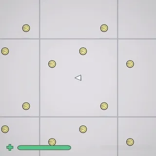
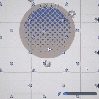
For the game, we created two effects: the reduction effect shown above, and an explosion wave effect.
The principle:
- Add a full-screen post-effect to the render pipeline.
- The post-effect relies on a second image that contains distortion information (equivalent to a normal map but indicating an offset for each pixel rather than an inclination). This shader will sample the original image by applying the indicated offset.
- The second image with distortion information is generated via a second camera on a dedicated layer that renders into a RenderTexture.
The Post Effect
In Unity 6 with URP, the full-screen Post Effect can initially seem more complex than before. In built-in rendering, you would typically create a script that overrides OnRenderImage and uses Graphics.Blit with the source and destination textures provided by the API. Unfortunately, this method is no longer available in URP, and the new functionality for performing this post-effect operation is called a Render Feature.
At this point, panic sets in during the jam: what? Implement a ScriptableRendererFeature that will itself require implementing a ScriptableRenderPass?
But fortunately, we can find a shortcut directly in the interface. Here's how it works:
Configuring the render pipeline
With URP, the render pipeline is configured via two configuration objects that are by default in the Assets/Settings folder:
- A Universal Render Pipeline Asset
- A Renderer2DData (for a 2D project, but there's an equivalent for 3D as well)
In this second file, we add a FullScreenPassRendererFeature by pressing the dedicated "Add Renderer Feature" button at the bottom of the inspector.
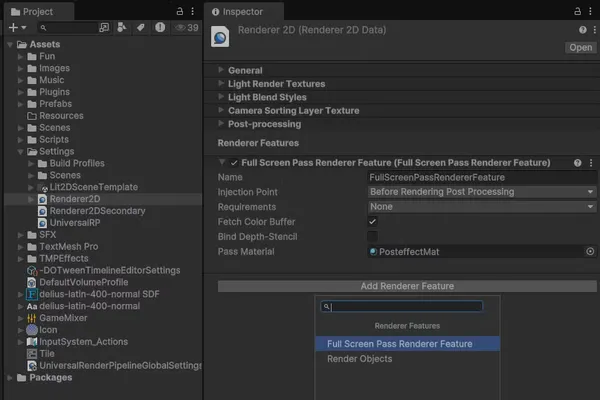
Project View: select the Assets/Settings/Renderer2D asset. Inspector view: use 'Add Render Feature' button then 'Full Screen Pass Renderer Feature'
We use the following configuration:
- Name: as you like (here I kept the default value)
- InjectionPoint: by default "After Rendering Post Processing", but for our game it didn't work because we add a bloom as a post-effect, and the distorted bloom looks very bad! So for this effect, I recommend injecting "Before rendering Post Processing" so that other post-effects are applied to the distorted image.
- Fetch Color Buffer: checked! This adds a copy pass but we need the initial colors to create our distortion effect.
- Bind Depth-Stencil: unchecked. The depth stencil controls the depth and masking of pixels during 3D rendering. For our 2D rendering, we won't use it here.
- Pass Material: the instance of the Post Effect Shader material.
Let's see how to create this shader and its material!
The Post Effect Shader
Shader Initialization
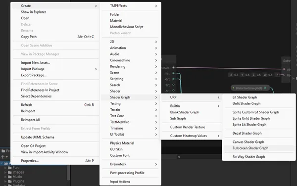
To create the shader, in the project view: right-click > Create > Shader Graph > URP > Fullscreen Shader Graph. This will create a preconfigured shader for a full-screen post-effect.
Once in the shader graph, we have the output point (The fragment Base Color) but the entry point is not obvious. We find it in the official documentation: https://docs.unity3d.com/Packages/com.unity.render-pipelines.universal@17.0/manual/post-processing/post-processing-custom-effect-low-code.html
As indicated, we create a URP Sample Buffer node configured with the BlitSource source.
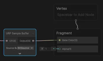
This configuration gives us a Post Effect that simply copies the original pixels. On the URP Sample Buffer node, the pixel information source is obtained from a UV value which by default is a screenspace UV ((0,0) at the bottom left of the screen and (1,1) at the top right).
Offset Effect
Modifying this UV will allow us to choose for each pixel to pick the source pixel offset to create the desired effect. For projectiles, a "shrinking" texture will concentrate the reading of pixels towards the middle, and conversely for the explosion, we will push the reading outwards.
We will start with the following conventions for the information texture:
- The R and G channels will contain the offset information on the X and Y axes respectively.
- As negative colors don't exist, we will normalize as for a normal map:
0.5is the neutral value, below we offset in the negative, above we offset in the positive.
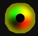
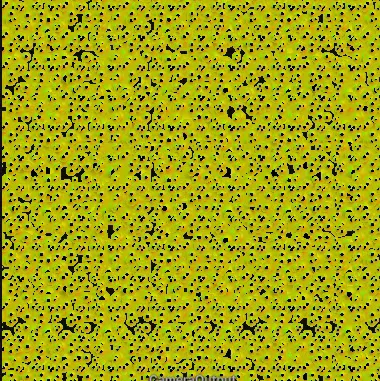
The images below represent the distortion textures of the projectile and the explosion effect. For the projectile, for example, if we focus only on the red value, we see that starting from the left edge, the color is neutral (red 0.5) then transitions more and more strongly towards black as we approach the center (where green remains alone since there is no more red), and on the other side of the circle the opposite happens, we quickly go from an intense red near the center (1) to a neutral red (0.5) going towards the right edge.
The intensity of black/red at the center indicates that the effect will be strongest near the projectile, and thus lighter near the edge. The stronger the intensity (black or red), the further we will look for the pixel to read in the source texture to the left or right. This will create a shrinking effect around the particles by fetching pixels further around.
For the magnifying effect, on the contrary, we will seek to display pixels closer to the center, which will push and stretch the pixels of the source texture from the center outwards.
Shrinking texture example. Black dot in the center matches the projectile shape, shrinking only the surrounding but not the projectile itself.

Shader Programming
We set up the shader as follows:
- A _Secondary parameter of texture type which will be our source of information. Eventually, this texture will contain only red and green information as shown above.
- A SampleTexture2D node to read the information from this texture
- We subtract 0.5 from each source channel to obtain a value between -0.5 and 0.5
- We add a UV node (channel UV0) as the UV source
- We add the result of the subtraction to the UV to get the offset UV
- We use the offset UV (result of Add) as the UV source of the URP sample buffer
- We can introduce a float DistortionStrength parameter to configure the amplitude of the offset, we multiply it with the result of the subtraction before adding it to the UV
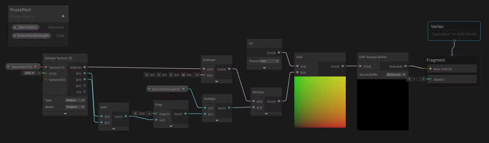
Below is the complete graph which includes an additional operation: if the source image is very close to black (Add(R+G) → Step(threshold of 0.1)) we consider that we have no offset information and we cancel the offset (multiplication by 0 which cancels any offset).
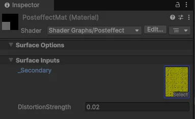
Material Configuration
We can now configure the shader material in the Renderer2DData:
- To create the material, in the Project view, right-click on the shader > Create > Material. This creates a material automatically attached to the shader.
- We attach the material in the Renderer2DData inspector
- We configure the material
Here I'm testing with an orange texture (red=1, green=0.5), the entire image is shifted to the left when we increase the distortion strength.
- The value of the red channel is close to 1 which shifts the reading more to the right. The UV coordinate is shifted more to the right, so the pixel sampled by the
Sample Buffernode is further to the right in the source, which shifts the rendered image to the left and leaves a black band on the right (there are no more pixels to read when we go out of the rendering area of the source texture! → black rendering). - The value of the green channel is close to 0.5, no vertical change since we apply no offset to the original UV
All that's left is to generate this distortion texture to get something more interesting!
Generating the Distortion Texture
Here are the setup steps:
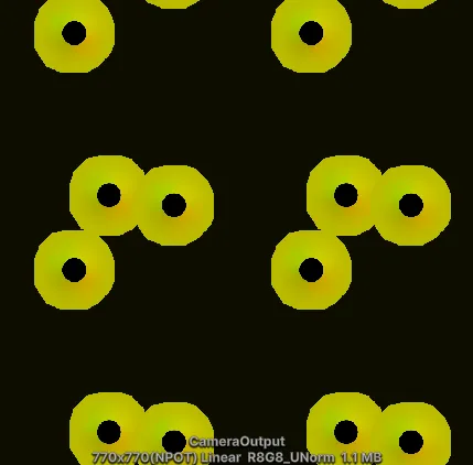
- Create a RenderTexture asset (here named "Camera Output") that respects the target ratio in R8G8_UNORM
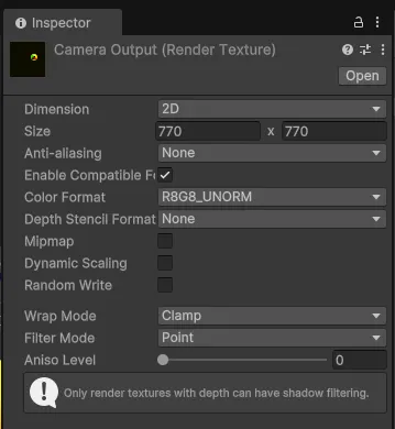
Camera Output Render Texture.- Create a dedicated layer (here named "Secondary")
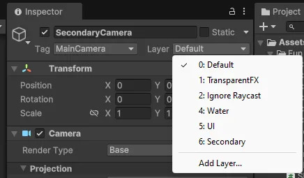
- Create a secondary camera that only films secondary and ignores the rest (culling mask)
- For this camera, you'll need to create a Renderer2DData (named e.g. Renderer2DSecondary) inspired by the first Renderer2DData we had previously but which disables all post effects
- Add this renderer2DData to the renderer list of the Universal Render Pipeline Asset
- Configure the secondary camera to use this renderer (Rendering > Renderer > Renderer2DSecondary)
- Configure the output to use the RenderTexture created previously (Output > Output Texture >
Camera Output)
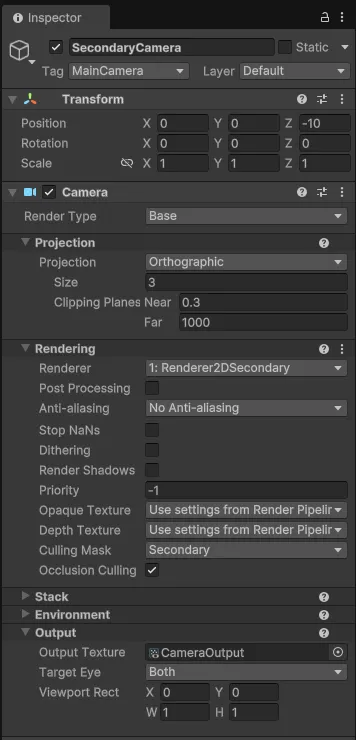
- Configure the main camera to ignore secondary (Rendering > Culling Mask > uncheck
Secondary) - In the projectile prefab, add a distortion sprite set on the "Secondary" layer
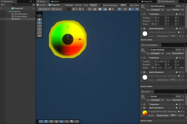
- Projectile is an empty gameobject that serves as a parent for the elements
- SpriteRenderer is a Sprite Renderer, the normal rendering of the sprite on the Default layer
- ProjectileMask is a Sprite Renderer of the same sprite but completely black on the Secondary layer. By displaying over Shrink, it prevents the distortion effect from being applied to the projectile itself (otherwise it would appear all shrunken).
- Shrink is a Sprite Renderer of the effect that is rendered on the Secondary layer. This is the distortion effect. It's about 3 times wider than the projectile itself so that the effect area is around the projectile.
As part of our game Powered By Geometry, I also programmed an additional shader to generate the distorted UV texture that we can observe above, but it's also possible to use a pre-calculated sprite.
For the explosion effect, I use a particle emitter configured on the Secondary layer that animates the enlargement and then fadeout of a single large particle, similar to that of projectiles except that the colors are inverted, to give a pushing effect rather than a converging effect.
Finalization
Everything is ready! The last step is to set this RenderTexture (Camera Output) as the _Secondary value of the material created previously.
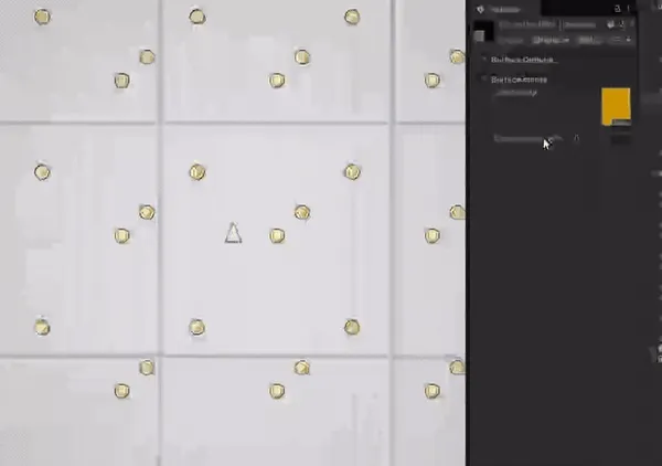
When there are projectiles on screen, it might look like this:
And for a preview of the final rendering when there are lots of particles all over the screen, why not test the game? It's available for free and should run performantly in your browser thanks to the WebGPU export:
https://itooh.itch.io/powered-by-geometry
You might be reading this article from a mobile, so here is a small extract of the wavy effect that we can guess despite the compression artifacts, giving a somehow aquatic look to the scene!
That's it, if you liked the writing, don't forget to follow me on your favorite network for more!